

Products Intelligent Fire Alarm System Addressable MCP, Sounder Strobe, Modules & Repeter Details
Details
Intelligent Input Module:CFT-952
I. Overview
The CFT-952 Intelligent input module (CFT-952 module for short)is used with CFT-MN300,a two-bus fire alarm control panel. It can be connectedwith a conventional smoke detector, a conventional heat detector, a conventionalmanual call point, a conventional hooter/horn and some other equipment. Afterthe said equipment starts to operate, the alarm signal output will be sent bythe CFT-952 module to the fire alarm control panel through a signal bus to givea fire alarm.
II. Features and technical parameters
1. Modeof operation: Nonpolar two-wire system
2. Quiescentcurrent: <0.5mA(bus); <6mA (power line)
3. Action current: <2mA (bus); <15mA (power line)
4. Operationindicator: The inspection indicator will blink once about every 12 seconds inthe inspection status or remain lit in the operation status.
5. Operating environment: Temperature: -10℃~50℃; relative humidity: ≤95% (40℃±2℃, without condensation)
6. Terminalload: 4.7K resistance
7. External dimensions: 86×86×40(mm)
8. Weight:about 119g
9. Executivestandard: GB16806-2006
III. Instructions for use
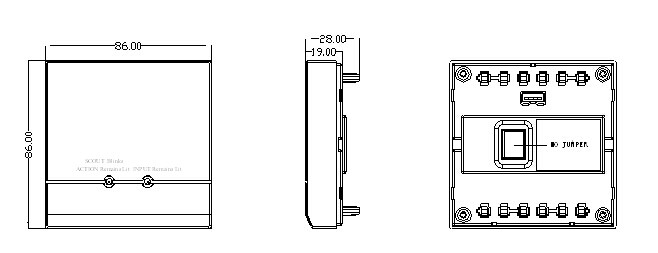
Fig.1 Main Body of the CFT-952 Module
1. Terminal description forthe CFT-952 module (see Fig.2)
Terminal description:
Terminal No. | Function | Description | Terminal No. | Function | Description |
1 | +24V | DC24V access terminal (positive) | 4 | TO+ | Load access terminal (positive) |
2 | GND | DC24V access terminal (negative) | 9 | L1 | Access terminal for the bus signal of the fire alarm control panel |
3 | TO- | Load access terminal (negative) | 10 | L2 | Access terminal for the bus signal of the fire alarm control panel |
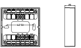
Fig.2Base of the CFT-952 Module
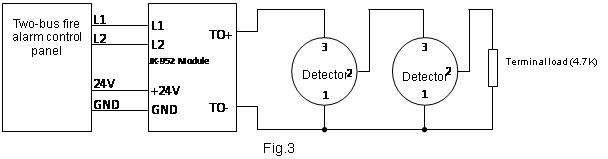
2. Wiring method of the CFT-952module
1) Connectionwith a detector (see Fig.3)
2) Connectionwith a manual alarm button (or a hydrant button) (see Fig.4)
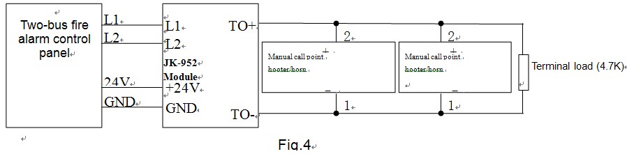
Note:The 24V power supply may be a DC24V provided on site; when in use, the CFT-952module must be connected to a 4.7K terminal load.
IV. Installation and debugging
1 Make sure the type of the module matches the type given on the construction drawings.
2. Connectthe 4-pin coding plug on the coder with the 4-pin coding socket (see Fig.1) onthe main body of the CFT-952 module, and then set the coder with the codingfunction and compilethe correct address code to finish the address coding.
3. Conduct correct wiring as instructed inFig.3 or Fig.4.
4. Use two M4 screws to fix the module base via the two ellipticscrew holes shown in Fig.2, then insert the main body of the CFT-952 module into the module base and make sure they contact eachother properly.
5. After the CFT-952module isinstalled and checked, connect the power supply of the fire alarm control panel.Upon successful login, the inspection indicator of the CFT-952 module will blink once about every 12 seconds, whichsuggests that the CFT-952 module has begun to operate.
6. Conduct debugging after the installationis completed. Connecting the equipment to the CFT-952 module results in an operation signal or simulates the operation signal ofthe said equipment. After that, the CFT-952 module can send the operationsignal to the fire alarm control panel and have its indicator lit, which suggests that the CFT-952 module has begun to operate.
7. Afterdebugging, reset the CFT-952 module and related equipment.
V. Precautions
1. Whenconnecting the CFT-952 module with a detector, a manual alarm button or ahydrant button, do not connect the positive and negative poles inversely.
2. Atmost, 50detectors can be connected in parallel with a CFT-952 module and upto 10 detectors can give an alarm at thesame time. If all the detectors give an alarm at the same time, those with deficientindicator luminance will fail to display the alarm status correctly.
3. Do notmake two or more products in a single circuit share the same address or thesystem will report a coincident code fault.
4. Confirmthe type of the external equipment connected to the CFT-952 module (feedback equipment or fire alarmequipment) and have the corresponding equipment type of the CFT-952 module setin the fire alarm control panel. After automatic login, the CFT-952 module willtreat the external equipment as fire alarm equipment by default.
