

Products Intelligent Fire Alarm System Addressable MCP, Sounder Strobe, Modules & Repeter Details
Details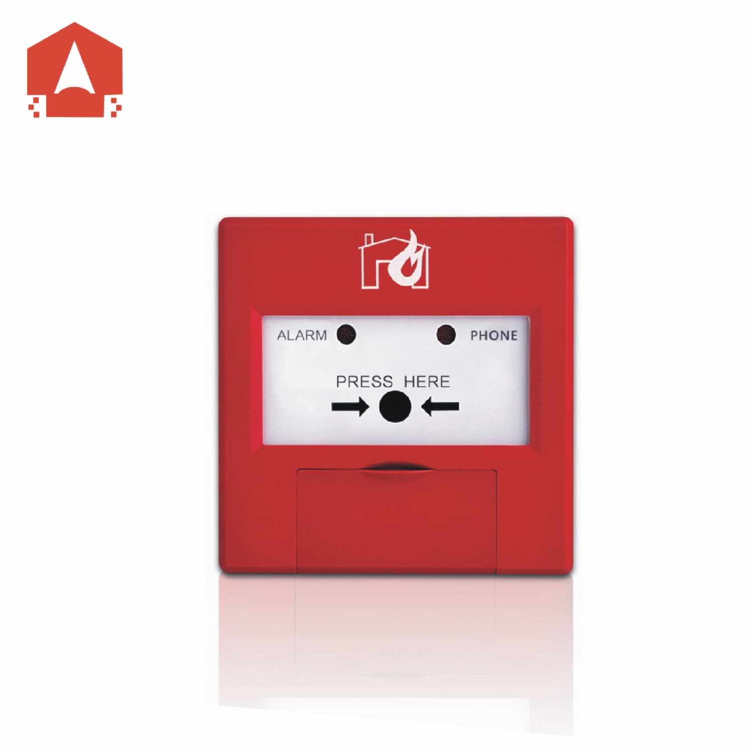
Addressable Manual Call Point:CFT-960
I. Product overview
The CFT-960 addressable manual callpoint (manual call point for short) is mainly designed to be used with an intelligenttwo-bus control panel. If it is pressed after a fire is manually confirmed, analarm signal may be sent to a fire alarm control panel which will, afterreceiving the alarm signal, display the coded address and the equipment statusof the manual call point. When the manual call point is operating normally, thered indicator will blink; when there is a fire alarm, it will remain lit. The manualcall point supports electronic coding and has a built-in fire telephone jackand a PHONE indicator, making its engineering application convenient.
II. Product features
* It can realize complete electronic coding and in situ rewritingwith help of a coder.
* Designed with an upper cover and a lower cover, it can beinstalled, debugged and maintained conveniently.
* It is designed with a two-wire fire telephone jack and istherefore more applicable to engineering application.
* Designed with passive output contacts, it can control otherexternal equipment directly through an intermediate relay.
* The pressing sheet on the manual call point will not getcrushed after it is pressed, but can be reset by a specialtool, so it can be used repeatedly.
III. Technical parameters
1. Executive standard: GB19880-2005
2. Operating voltage: 24V (pulse modulation)
3. Operating current: <300uA (inthe monitoring status); <2mA (in the action status)
4. Output contact: Normally open contact; capacity: 0.1A/30VDC
5. Weight: About 120g
6. Wiring method: nonpolar two-bus system (L1, L2)
7. Operating environment: Indoor, temperature: -10℃~+50℃; relative humidity: ≤95% (40℃±2℃, withoutcondensation)
8. Coding method: It can realize online coding with thehelp of acoder and without the necessity of disassembling the bus (however, theequipment must be powered off). Address codes 1 to 324 are available for selection.
9. Telephone jack: Two-wire fire telephone jack (equipped witha standardФ6.3 single-track audio connector).
10. Starting part: A plastic pressing sheet that may be usedrepeatedly. It can be manually reset with a special tool after being pressed.
11. Starting mode: Press the pressing sheet manually.
12. Indicator: The red ALARM indicator will blink in theinspection status or remain lit in the alarm status; the PHONE indicator willblink when a fire telephone loop is connected, otherwise it will be out.
13. Matched host machine: fire alarm control panel (such as CFT-MN300)
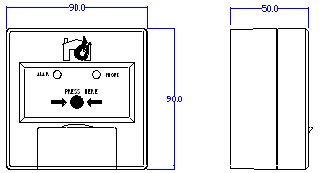
IV. Appearance and dimensions (seeFig.1)
V. Use and engineering application
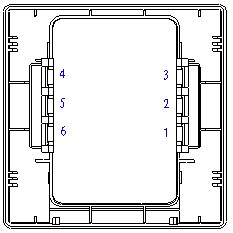
1. Fig.2 is the schematic diagram of theterminals on the rear cover of the manual call point.
| Definitions of terminals: 1 --1. Signal terminal (L1) 2 --2. Signal terminal (L2) 3 --Normally open contact (closed with the terminal 4 during operation) 4 --Normally open contact (closed with the terminal 3 during operation) 5 --Connecting terminal for the fire telephone line (TL2) 6 --Connecting terminal for the fire telephone line (TL1)
|
2. Fig.3 shows the general functions and wiringdiagram of the product.
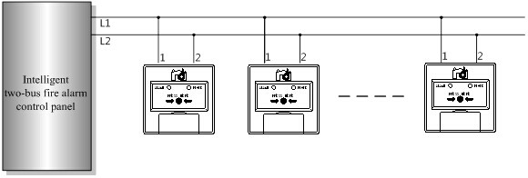
Fig.3
3. Fig.4 shows the extended functions and wiringdiagram of the product.
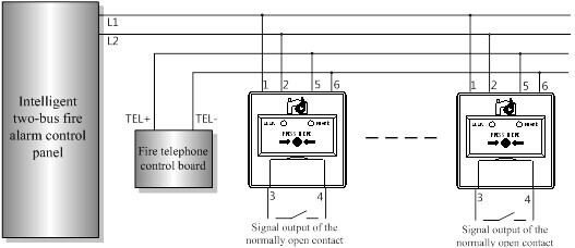
Fig.4
4. Usage of the manual call point:
Alarm:After a fire alarm is manuallyconfirmed, press the pressing sheet on the panel of the manual call point (seeFig.5). After that, a manual fire alarm will be given and the terminals 3 and 4of the normally open contact will be closed (see Fig.4) at the sametime. After the manual fire alarm is given, the ALARM indicator will remainlit.
Reset: Open the small movable panel onthe panel of the manual call point (see Fig.5) and then press the RESET key gentlywith a special tool to restore the pressing sheet that has been pressed to itsoriginal status. Reset the fire alarm control panel and restore the manual callpoint to the normal monitoring status.
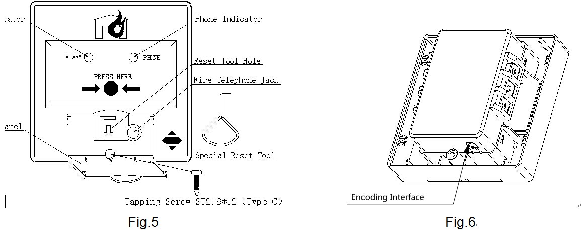
Firetelephone: Open thesmall movable panel (see Fig.5) and expose the fire telephone jack.Communication may be realized after the hand-held fire telephone connector isinserted into the fire telephone jack.
5. Address coding: Insert the coder’s outputconnector (aФ3.5 phoneplug) into the coding jack (see Fig.6), set the coder with the coding function,compile the correct address code and press the RUN key to complete the addresscode setup. Note: See the User’s Manual of the coder for detailed operation.
VI. Installation and debugging
Decideon the installation location, installation spacing and quantity of the manualcall point(s) according to relevant provisions and regulations of nationalstandards Code for Design of Automatic Fire Alarm System (GB50116-98) and Codefor Installation and Acceptance of Fire Alarm System (GB50166-2007).
Aspecial base is necessary during the installation of a manual call point. Asshown in Fig.7, the external dimensions, the mounting hole diameter and themounting hole spacing of the special base are 90mm×90mm×30mm (L×B×H), 5mmand 58mm~66mm respectively. The cableprotection pipe goes through the mounting hole from the bottom of the specialbase.
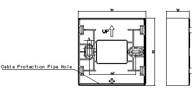
Fig.7
Wiringrequirement: It is proper to use RVS twisted pairs with a section of area ofequal to or larger than 1.0mm2for the signal buses L1 and L2.
Specific installation and debuggingmethods:
1、 Use two M4 screws to fix the matched mountingbase on the designated position via the mounting holes A and B shown in Fig.7,as instructed in the construction drawing, and make sure the matched mountingbase has been firmly installed.
2、 Make sure the type of manual call pointmatches the type of the host machine of the fire alarm control panel.
3、 Use a coder to code the manual call pointaccording to the manual call point address code on the construction drawing.
4、 Disconnect the power supply of the fire alarmcontrol panel and connect the manual call point correctly, according to theconstruction drawing.
5、 Insert the upper cover of the manual callpoint into the base and make them fit closely, then tighten the tapping screwshown in Fig.5.
6、 After all the products are installed andchecked, connect the power supply of the fire alarm control panel and conductautomatic login.
7、 After normal automatic login, the redindicator of the manual call point will blink once about every 12 seconds, whichsuggests that the manual call point has begun to operate normally.
8、 Give alarms and conduct a reset test normallywith the usage of the manual call point (see section 4 of V) and connect thefire telephone to test the effect of calling.
VII. Precautions
1. A manual call point cannot share an addresswith other equipment in a single bus circuit, or else an address conflict mayoccur.
2. Online coding may be done for the manual callpoint without the necessity of disassembling the wire connected with the hostmachine, but it is necessary to power off the host machine or the equipmentfirst.
3. Be careful when opening the small movablepanel to avoid damaging it.
4. The equipment needs to be reset through aspecial tool after operation. Please return the special tool for the resetafter the system returns to normal after debugging.
5. The installation of the manual call pointshould comply with relevant provisions of national standards Code for Design ofAutomatic Fire Alarm System (GB50116-98) and Code for Installation andAcceptance of Fire Alarm System (GB50166-2007).
VIII. Maintenance
Warning: Before conducting maintenance on a manual call point, inform related managementdepartments of the systemmaintenance and the necessity of stopping work for some time because of this. Meanwhile,disable the logic control function of the area or system to be maintained toavoid unnecessary alarm linkage. After the test, reset the manual call pointwith a special tool for reset and inform the management department that it can restore the normal functions of the system.
1. For a manual call point, at least annualtests should be done according to related provisions of national standard Codefor Installation and Acceptance of Fire Alarm System (GB50166-2007); for a manualcall point that has been installed and used, it is recommended to have itcleaned and maintained once every two years.
2. After the pressing sheet of the manual callpoint is pressed, the red FIRE indicator should be lit and the fire alarmcontrol panel should display the address corresponding to the alarm.
3. If a manual call point fails due to amaterial defect or a manufacturing process defect under the specified normalconditions of use in one year following the date of its delivery, we shallrepair or replace it for free. However, the faults of the manual call point dueto artificial damage, improper use or unallowed adjustment, reconstruction ordisassembly are not covered in the guarantee range and we shall assume no responsibilityfor any consequences thereby caused.
4. We may provide a paid-for repair service forthe products with any faults not covered in the guarantee. If you have suchproducts that need repair, please contact us. When sending such a product to usfor repair, you are expected to provide some important information about theproduct, such as the phenomenon and possible cause of the product fault, sothat we can find out the cause of the fault in the shortest time. Theinformation may be used as a reference in our future product development andimprovement.
IX. Fault analysis andtroubleshooting
Fault phenomenon | Possible cause | Troubleshooting method | Remarks |
Coding fails. | The internal circuit is damaged. | Send the product back to the factory for repair. |
|
The product cannot be logged into normally. | The product is not coded, or it has a coincident code. | Recode the product. |
|
The product reports a fault after login. | The internal circuit is damaged. | Send the product back to the factory for repair. |
|
The product reports a fire alarm after login. | The button has been started. | Reset the button. |
|
The internal circuit is damaged. | Send the product back to the factory for repair. |
|
