

Products Intelligent Fire Alarm System Addressable MCP, Sounder Strobe, Modules & Repeter Details
Details
Addressable Horn/strobe:CFT-991
I. Product overview
The CFT-991 addressable horn/strobe(horn/strobe for short) is a kind ofproduct manufactured by our company to be used with bus-type fire alarm controlunits. Controlled by a microprocessor, the horn/strobe can realize real-timecommunication with a bus-type fire alarm control unit and receive the controlcommands sent by it. When in a routing inspection, the red status indicatorwill blink; after an accident happens, the horn/strobe will start to operateafter receiving a startup command from the bus-type fire alarm control unit. The red status indicator will remain lit and the horn/strobe will give aflashing signal and an audible alarm signal to notify the persons on the scene of the accident that a fire has occurred on thesite and of the necessity to take related evacuation measures, thus preventing thefire accident from becoming a major one. The horn/strobe may be restored to the monitoring status after the MUTE or RESET key on the bus-typefire alarm control unit is pressed.
The horn/strobe may be used togive audible alarms and flashing alarms on the scenes of accidents. It is suitable for places like high-rise residential buildings, public places, hotels,amusement buildings, factories, shopping centers, hospitals, schools, officebuildings and stock exchanges, particularly places with low visibility or thepossibility of generation of smoke.
II. Product features
* It can realizecomplete electronic coding and in situ rewriting with the help of a coder.
* The audiblealarm and flashing alarm may be set freely. In other words, the horn/strobe maygive an audible alarm and a flashing alarm at the same time or separately andit can be adapted to different working environments.
* Designed with an upper cover and a lowercover, it can be installed, debugged and maintained conveniently.
* It uses multiplesuper bright red LEDs as light sources for visual display, ensuring a strikingdisplay, a longer service life and low power consumption.
III. Technical parameters
1. Executivestandard: GA385- 2002
2. Operating voltage: DC24V (pulse modulation)
3. Operatingcurrent: quiescent current: ≤1mA (the current consumed by the bus); alarmcurrent: ≤120mA@DC24V
4. Operatingenvironment: Temperature: -10℃~+55℃;relative humidity: ≤95% (40℃,without condensation)
5. Flushing rate: onetime/s
6. Alarm volume: >85dB (measured at a place 3min front of the horn/strobe)
7. Coding method:Electronic coding
8. Wiring method:Four-wire system, non-polarity two signal buses (L1, L2) and power lines (+24V,GND)
9. Matched hostmachine: fire alarm control panel (such as CFT-MN300)
IV. Appearance and dimensions (see Fig.1)
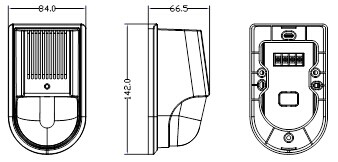
Fig.1
V. Use and engineering application
1 Fig.2 is theschematic diagram of the rear cover of the horn/strobe.
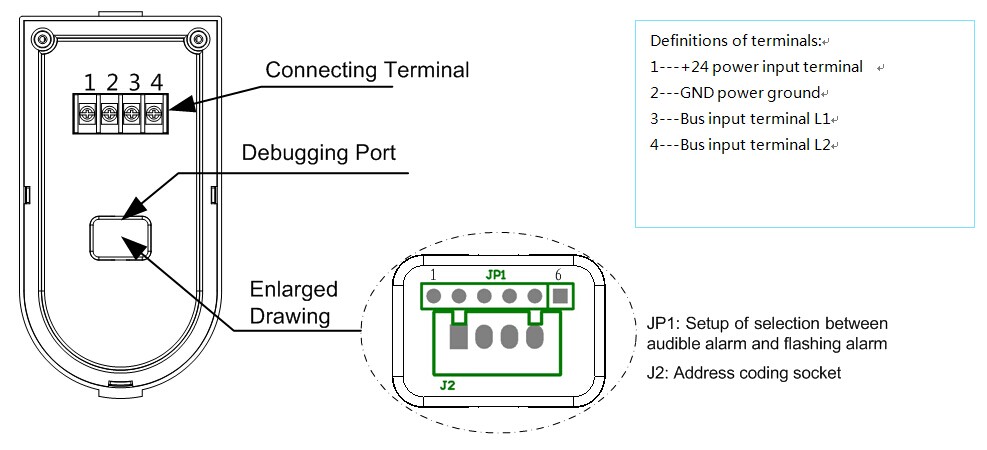
Fig.2
2. Selectionbetween audible alarm and flashing alarm: Select through the jumper (JP1) belowthe debugging port lid on the back of the horn/strobe, following theinstructions of the jumper.
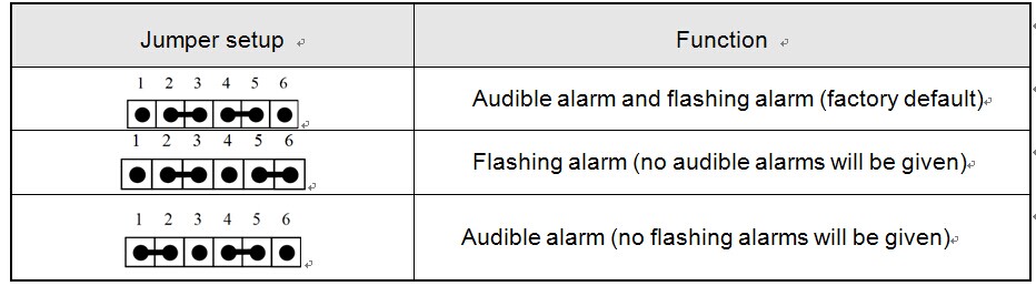
Warning: The output mode of a horn/strobe can be one of the three optionsin the table above only.
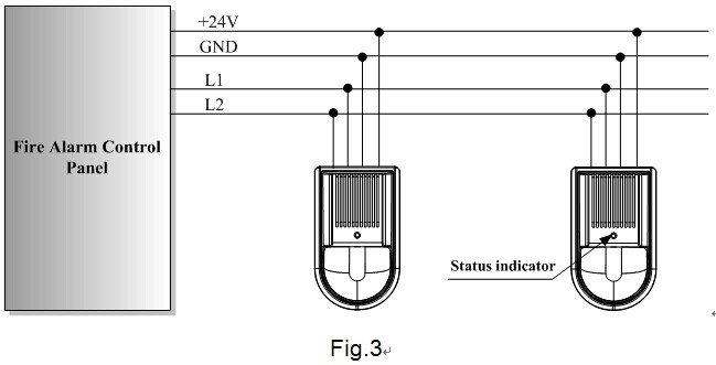
3. Fig.3 shows the general functions and wiringdiagram of the product.
4. Address coding: When a horn/strobe is coded,it is unnecessary to disassemble the wire connecting it with the host machine;online coding may be done. The specific method is as follows: Open the cover ofthe coding setup window, insert the output plug (a four-pin connector) of thecoder into the address coding socket (the socket J2 in Fig.2) of the horn/strobe, set the coder with the codingfunction, compile the correct address code and press the RUN key to completethe address coding. (Note: See the User’s Manual of the coder for detailedoperation information.)
Warning: It is necessary to have “onlinecoding” done when the system is powered off or related equipment may bedamaged.
5. Usage:Do not connect the power supply until the address of the horn/strobe has beenset and confirmed and the fire alarm control panel has been properly connected.After the fire alarm control panel is successfully reset, the red statusindicator (see Fig.3 for its location) of the horn/strobe will blink. After thehorn/strobe receives an operation signal, the status indicator will remain litand the horn/strobe will give both horn/strobe alarm signals. After the systemis muted or reset, the horn/strobe will stop outputting horn/strobe alarmsignals and the status indicator will start to blink again.
VI. Installation and debugging
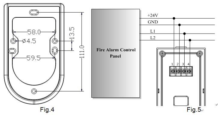
A special baseis necessary during the installation of a horn/strobe. As shown in Fig.4, theexternal dimensions of the special base are 142×84×10mm (L×B×H). The horn/strobe is subject to afour-wire non-polarity connection: Terminals1 and 2 are respectively connected with the terminals +24V and GND of the DCpower supplyterminals 3 and 4 are respectively connected with theterminals L1 and L2 of the signal bus of the fire alarm control panel. SeeFig.5.
Specificinstallation and debugging methods:
1. Use two M4screws to fix the matched mounting base on the designated position via themounting holes shown in Fig.4 (the installation may be done horizontally orvertically. Choose any two of the six mounting holes for installation) asinstructed in the construction drawing and make sure the matched mounting basehas been firmly installed.
2. Disconnect thepower supply of the fire alarm control panel and connect all the basescorrectly in the way shown in Fig.5, which is aconstruction drawing.
Note: When there are a lot of horns/strobes in a system, it is necessary to consider the loadingcapacity of the power supply of the fire alarm control panel. An external DC24Vauxiliary power supply might be necessary at this time. Please follow theconstruction design drawings.
3. Make sure thetype of the horn/strobe matches the type given on the construction drawings.Use a coder to code the horn/strobe according to the address code marked on theconstruction drawings.
4. After all the horns/strobesare installed and checked, connect the power supply of the fire alarm controlpanel and conduct automatic login.
5. After a horn/strobelogs into the fire alarm control panel, the red status indicator of the horn/strobewill blink; after the horn/strobe receives an operation signal, the red statusindicator will remain lit and the horn/strobe will give both horn/strobe alarmsignals. After the system is muted or reset, the horn/strobe will stopoutputting horn/strobe alarm signals and the status indicator will restore tothe monitoring status and start to blink again.
VII. Precautions
1. Pay attention to the marking and polaritiesof the terminals during installation and wiring.
2. Do not make different products share thesame address in a single alarm circuit or the system will fail to operatenormally.
3. Make sure during installation that there areno objects in front of the horn/strobe that block the light given by the horn/strobeand/or prevent the horn/strobe from sounding.
4. Make the installation comply with relatedprovisions of the Code for Installation and Acceptance of Fire Alarm System(GB50166-2007).
VIII. Maintenance and inspection
1. As specified in national standard Code forInstallation and Acceptance of Fire Alarm System (GB50166-2007), at leastquarterly tests should be done for each horn/strobe.
2. If a horn/strobe fails due to a materialdefect or a manufacturing process defect under the normal conditions of use inone year following the date of its delivery, we shall repair or replace it forfree. However, the faults of the horn/strobe due to artificial damages,improper use or unauthorized adjustment, reconstruction or disassembly are notcovered in the guarantee and we shall assume no responsibility for all theconsequences thereby caused.
3. We may provide a paid repair service for theproducts with any faults beyond the guarantee range. If you have such products needingrepair, please contact us. When sending such a product to us for repair, youare expected to provide some important information about the product, such asthe phenomenon and possible cause of the product fault, so that we can find outthe cause of the fault in the shortest time and the information may be used asa reference in our future product development and improvement.
IX. Fault analysis and troubleshooting
Fault phenomenon | Possible cause | Troubleshooting method | Remarks |
The horn/strobe cannot give a horn/strobe alarm signal. | The wiring is wrong. | Inspect whether or not the wiring is correct. |
|
The linkage function has not yet been enabled. | Inspect whether or not the general linkage indicator is lit. |
| |
The short-circuit block is set wrong. | Inspect whether or not the short-circuit block is correctly set and whether or not its contact is good. |
| |
The internal circuit is damaged. | Send the horn/strobe back to the factory for repair. |
|
