

Products Intelligent Fire Alarm System Addressable MCP, Sounder Strobe, Modules & Repeter Details
Details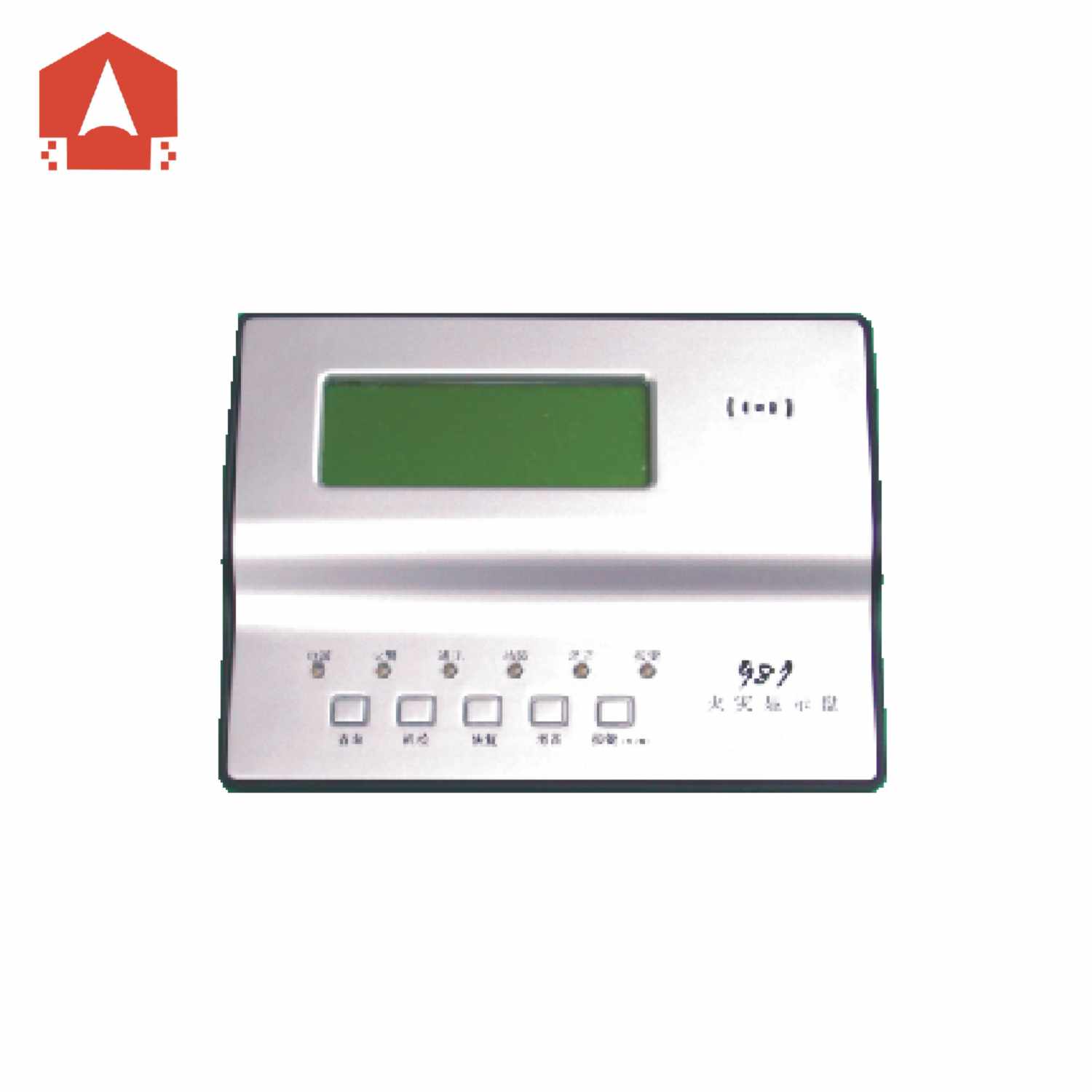
Fire Display Panel:CFT-982
I. Product overview
The CFT-982 fire display panel (displaypanel for short) is a kind of microprocessor-controlled fire display paneldeveloped by our company. Each display panel is connected to a fire alarmcontrol panel produced by our company via a special RS-485 interface to processand display the data sent from the fire alarm control panel. Each floor of abuilding may have a display panel installed. When there is a fire alarm on thefloor where the display panel is installed, or the neighboring floor above orbelow it, the display panel will give a horn/strobe alarm and display the floorNo., the room No., and some other position information of the fire alarm.
II. Product features
* Each display panel is connected with a fire alarm controlpanel via a RS-48 bus. At most 99 display panels may be connected with eachRS-485 bus.
* The display panels can display fire alarm messages orfeedback messages only rather than fault messages, action messages or othermessages.
* A fire alarm control panel may be used for setting thedisplay area of a display panel. The set display panel can display the firealarm messages of the designated area (floor display) only. Note: See the User’sManual of the fire alarm control panel for the setting method.
* It can replace a JB-FSD-981 fire display panel in a 2100system.
III. Technical parameters
1. Executive standard: General Technical Conditions for FireIndicating Panels (GB17429-1998)
2. Display capacity: Each display panel can display the firealarm messages of floors -10~90 and at most 99 fire alarm messages or feedbackmessages.
3. Wiring system: Four-wire system, power lines (+24V, GND) andRS485 signal lines (485A, 485B)
4. Operatingenvironment: Indoor; temperature: -10℃~+50℃; relative humidity: ≤95% (40℃,without condensation)
5. Power supply: DC 24V ±20%
6. Overall power consumption: <3W
7. Contact capacity: Relay dry contacts, normally open ornormally closed, capacity: 1.25A/DC30V (resistive load)
IV. Appearance and dimensions (seeFig.1)
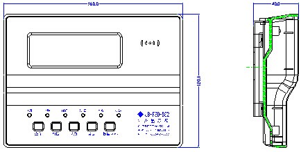
Fig.1
V. Use and engineering application
1. Fig.2 is the schematic diagram of the terminals of a displaypanel.
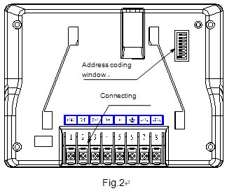
Definitions of terminals:
1 --+24V (positive input terminal of the power supply)
2 -- GND (negative input terminal of the power supply)
3 -- OFF (terminal for the normally closed contact of the relay)
4 --COM (common terminal for relay contacts)
5 -- ON (terminal for the normally open contact of the relay)
6 -- (earth terminal of the equipment)
7 --485A (485 bus input terminal)
8 --485B (485 bus input terminal)
2. Fig.3shows the general functions and wiring diagram of the product.
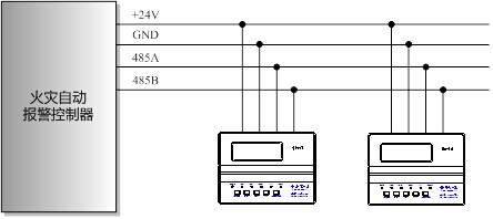
Fig.3
3. Functionsand usage of the product:
1)The displayed content
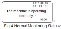
If the display panel operates normally after startup, “The machine is operatingnormally,” as shown in Fig.4 will be displayed. The current date and time are displayed at the top right corner ofthe screen. The time is synchronous with that of the host machine of the firealarm control panel and is refreshed by it (there is some interval forrefreshing). The currently supported control system is displayed at the lowerright corner of the screen. If “2100” is displayed, it means that a 2100control system is supported; if 9000 is displayed, it means that a 9000 controlsystem is supported. The specific control system supported depends on the eighth digit of the address dial switch onthe back of the display panel. For more details, see 10) Setup of addressparameters and control system.
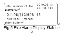
The display panel can display 99 fire alarm messages or feedback messages. When setto the floor display mode, each display panel can display all the fire alarms of the floor. When there are multiple fire alarms, the equipment will displaythem in an automatic rolling way. See Fig.5 for the interface.
2) Display and statuses of indicators
Name | Color | Description |
POWER | Green | If the power supply is normal, the green POWER indicator will remain lit. |
FIRE | Red | It is out at ordinary times and will be lit in case of any fire alarm(s). |
COMMUNICATION | Green | It blinks under normal circumstances and is out in case of a communication fault. |
FAULT | Yellow | In case of an equipment fault, the yellow FAULT indicator will be lit. |
MUTE | Green | It will be lit after the system or the equipment is muted. |
KEY | Green | If it is lit, it suggests that the keyboard lock is unlocked and all key functions are enabled; if it is out, it suggests that the keyboard lock is locked. |
3) Functions of the keyboard lock
Keys SYSTEM TEST, QUERY, and RESET can be operated only when thekeyboard lock is unlocked, otherwise they cannot. After a combined password isset for the keys and keys KEY (ENABLE/DISABLE), RESET andQUERYare pressed once in order, the keyboard lock will be unlocked and the KEY indicatorwill be lit. After the KEY (ENABLE/DISABLE) is pressed againafter that, the keyboard lock will be locked again and the KEY indicator willgo out.
4) Muting
After the SYSTEM MUTE key is pressed, the firealarm tone will be eliminated, the MUTE indicator will be lit and the normallyclosed contact of the relay will be closed. Afterreceiving another fire alarm, another horn/strobe alarm signal may be triggeredand the MUTE indicator will go out automatically.
Note: After receiving a MUTE command from an automatic firealarm control panel, the display panel can also realize the muting function.
5) System test
After the SYSTEM TEST key is pressed after thekeyboard lock is unblocked, all the indicators on the display panel will belit, the buzzer will buzz and the LCD backlight will be lit too. Two secondslater, all the indicators (except for the POWER indicator) will go out, thebuzzer will stop buzzing, the system test is completed and the equipmentrestores the status before the system test.
Note: The system test function is disabled when there is afire alarm.
6) Reset
After the RESET key is pressed after the keyboardlock is unblocked, all the indicators (except for the POWER indicator) on thedisplay panel will go out, the fire alarm tone will disappear, the normallyclosed contact of the relay will get closed and all the fire alarm records ofthe equipment will be deleted.
Note: After receiving a RESET command from an automatic firealarm control panel, the display panel can also realize the reset function.
7) Query
After the equipment receives two or more fire alarmmessages, it will display the fire alarm messages automatically and circularly.After the QUERYkey is pressed after the keyboard lock is unlocked, the equipment will enterthe manual display status. Each time after the QUERY key is pressed, the equipment willdisplay the next fire alarm message. If the QUERY key is not operated within eightseconds, the equipment will automatically return to the circular displaystatus.
8) External relay
The equipment includes a group of relay external controlcontacts (normally open or normally closed). After the equipment receives afire alarm message, the external relay will be started. Status of the externalrelay: Under normal circumstances, OFF and COM are closed and ON and COM areopen; in case of a fire alarm, OFF and COM are open and ON and COM are closed.
9) Communication indication
When the display panel is communicating with the automaticfire alarm control panel normally, the COMMUNICATION indicator on the displaypanel is on, which indicators normal communication.
10) Setup of address parameters and control system
During the installation of the display panel, its addressmust be set according to the specific installation location. The address is setthrough a JP3 dial switch on the main board on the back of the display panel(see Fig.2 for its location). The JP3 dial switch has eight dial digits in all,wherein the first to the seventh digits are used for setting the address (seeFig.6 and Fig.7), and the eighth digit for choosing the 2100 control system orthe 9000 control system. If the JP3 dial switch is pulled to the ON position,the 9000 control system will be chosen (see Fig.6); if it is pulled to the OFFposition, the 2100 control system will be chosen (Fig.7). Corresponding contentis displayed at the lower right corner of the screen.
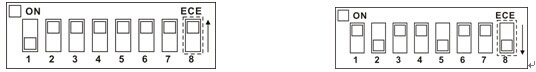
Fig.6 Address Codes of the 9000 ControlSystem Fig.7 Address Codes of the 2100 ControlSystem
If the short-circuit block is pulled to the ON position, the digit will be set to be “0”;if it is pulled to the OFF position, the digit will be set to be “1.” Address setup is calculatedthrough a binary coding method (popularly speaking, binary numbers like 1, 2,4, 8, 16, 34, 64 and so on are used). For example, if the JP3 dial switch isset to be “1000000” (see Fig.6), the address will be 1+0+0+0+0+0+0=1; and if itis set to be “0100100” (see Fig.7), the address will be 0+2+0+0+16+0+0=18.
VI. Installation and wiring
A special base is necessary during the installation of adisplay panel. As shown in Fig.8, the external dimensions, the mounting holediameter and the mounting hole spacing of the special base are 101.5mm×14mm×86mm(L×B×H), 4.5mm and 58mm~62mm respectively.
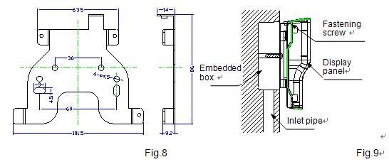
A JB-FSD-982 fire display panelconsists of a base and a display panel. It is subject to a wall-mountedinstallation. Its external wires may be directly connected with the terminalson the rear panel of the display panel. See Fig.9 for the schematic diagram ofthe mounting base of the display panel.
Base fixing: Fix the base of thedisplay panel on the embedded box.
Wiring: Connect the leads stretchingout from the junction box with the terminals on the display panel and do acorrect wiring according to the contents marked on the terminals.
Fix the display panel.
Arrange the guideslot on the back of the display panel so it aligns with the mounting base and press thedisplay panel with a downward force along the wall until the guideslot fits the mounting base perfectly. After that, lock the small hook on theupside of the back of the display panel with the guiding sheet on the mountingbase with some matched screws (see Fig.9).
Precautions
Please inspect whether or not thecircuit of the equipment suffers short circuit, open circuit, wrong wiring andother defects.
The display panel is a preciseelectronic product and therefore needs to be managed by a specific person. Noother persons are allowed to operate it without permission.
Please wipe the surface of theequipment with alcohol.
VII. Fault analysis and troubleshooting
Fault phenomenon | Possible cause | Troubleshooting method | Remarks |
The display panel fails to display or has an abnormal display after being started. | a. The power supply is abnormal; b. The connection with the fire alarm control panel is poor; or c. The LCD or the CPU are damaged. | a. Inspect the DC24V power supply; b. Inspect the power line; or c. Send the display panel back to the factory for repair. |
|
The equipment cannot be started. | The DC 24V power supply is not connected. | Inspect the DC24V power supply. |
|
The fire alarm control panel cannot be registered. | The RS-485 bus is poorly or wrongly connected. | Inspect the RS-485 bus and reconnect it. |
|
The display panel has abnormal communication. | The system chosen is not proper and the eighth digit of the dial switch is wrongly pulled. | Pull the eighth digit of the dial switch to the correct position. |
|
