

Products Intelligent Fire Alarm System Addressable MCP, Sounder Strobe, Modules & Repeter Details
Details
Operating Instructions:CFT-F900E
I. Introduction
Coder -F900E is aportable device for writing /reading address code of all intelligent terminalsour company produces, it’s a basic tool in the processes of device installing,debugging and servicing.
II.Features
1. Smallsize, shockproof and portable to take with;
2. Low powerconsumption, successive working duration is up to 18 hours;
3. Support2100/9000 intelligent terminal;
4. Automaticallyincrease the code based on previous, improve the work efficiency;
5. Battery level can be checked;
6. Over-dischargeprotection is provided;
7. Shortcircuit protection is provided;
8. Chargingindicator is designed;
9. Automaticallyenter power saving mode and power off in idle mode.
III. TechnicalParameters
1. Built-in1600mAh lithium battery;
2. External24V/500mA DC can be used as direct work power supply or to charge the battery;
3. Workingcurrent: 15mA—170mA, standby current: 15mA;
4. Ambient temperature: -20℃~60℃, relative humidity: 5%~95%.
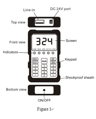
IV. Appearance
Refer to figure 1
Line-in: for attachedconnection line only to intelligent terminals such as detector, module or audibleand visual alarm;
Note: do NOT connect any other USB device!
24VDC port: for 24VDC/500mA power supply, inner is anodeand outer ring is cathode.
Note: do NOT disconnect the power plug in working state!
Screen: displays battery level, prompts and addresscodes that have been read out and wait for writing.
Indictors: fiveindicators are designed to indicate the statuses of power, reading, writing,switching and charging (from left to right).
Power—green: theindicator turns on when it is powered on or there is an external power supply;
Reading—red: the indicator turnson when it’s in reading mode;
Writing—red: theindicator turns on when it’s in writing mode,and blinks when it’s in autoincrease mode.
Switching—red: support9000 bus terminal when it turns off; support 2100 bus terminal when it blinks.
Charging—green: theindicator turns on when it’s in charging state and turns off then it’s fullycharged.
Keypad: 17 functional keys are designed including: select,delete, run, increase, decrease and numeric keys,etc.
MENU: press this key to select the function of writing orreading; long press this key to enter the mode of auto increase.
Delete: use in writing mode, press this key to delete the wrong codeentering.
Run: write and read the address code of the intelligentterminals.
Increase: use in writingmode, press this key once to increase one level, long press this key toincrease the address code successively.
Decrease: use in writing mode, press this key once to decrease onelevel, long press this key to decrease the address codesuccessively.
Numeric Keys (0-9): enter the address code to be wrote
“*” : check battery level, not available when there is anexternal power supply.
“#” : press this key to switch between 2100 system mode and9000 system mode.
Shockproof Sheath: reduce the impact with other hard objects,take it off when replacing battery.
V. Operations
1. ON/OFF
Long press “ON/OFF” key for 1 sec to power on the devicewith power indicator and writing indicator turned on, the screen displaysnumbers, the device enters working mode; when the device is in normal workingmode or power saving mode, press this key to power off the device and allindicators are turned off; when there is an external power supply, the powerindicator keeps turning on even in power-off state, at this moment, the usermay re-start the device by pressing this key.
2. 2100/9000 System Switching
It enters 9000 system as default when the device powers on;the user may press “#” key to switch to 2100 system, the screen displays “199” and the switching indicator blinks;further press “#” key to switch back to 9000 system, the screen displays “324” and the indicator turns off.
3. Battery Level
Press and hold “*” key to check the current battery level,10 levels (1-10) are designed, as shown below:

When the level shows , it means the battery is fully charged andcan be successively worked for 18 hours; when the level shows , it means the battery is half used; when thelevel shows , it means the battery is lower and needs tobe charged and the buzzer beeps a sound every 30 secs; when the level shows , it means the battery is used up and thedevice will automatically power off; at this moment pressing “ON/OFF” key couldn’t power on the device because the over-discharge protection isfunctioned, it must be charged immediately. The battery can be fully chargedwithin 5 hours; the charging indicator turns off when it’s full.
Note: the successive working time is subject to the actual workingconditions, 18H is an estimated value for reference only!
4. Writing
Connect terminal device by attached connection line and switchto applicable bus type. Press numeric keys to enter the address code, press Runkey to code; if the writing process succeeds, the screen displays the addresscode and a beep sound can be heard; if the writing process fails, the screen blinksto display , and three beep sounds can be heard, at thismoment the user is advised to check the system bus type and the connection ofthe device and terminal, then enter the address code and try to write again. press“Delete” key to delete wrong code entering.
5. Auto Increase of AddressCode
Press and hold “Select” key for 2 secs, the writingindicator blinks, the system enters the mode of auto increase. When a correctaddress is wrote, the screen blinks to display the address; at this moment theuser may disconnect the terminal device and the address increases automaticallyby one, press “Run” key to continue to write the address when installing thenext terminal device;it’s unnecessary to enter address for later writing.
6. Reading
Connect terminal device by attached connection line and switchto applicable bus type. Press “Run” key to read out the address, if the readingprocess succeeds, the screen displays the address and a beep sound can beheard; if the reading process fails, the screen blinks to display , and three beep sounds can be heard, at thismoment the user is advised to check the system bus type and the connection ofthe device and terminal, then read out the address again.
VI. Other Functions
1. Bus shortcircuit detecting, in case of bus short circuit, the buzzer beeps twice asecond till it recovers.
2. If no anyoperation is made within 1 minute, the screen would turn off and enter powersaving mode; in this state, press any key to turn on (except ON/OFF).
3. If no anyoperation is made within 5 minutes, the system would automatically power off;pressing“ON/OFF” key can re-start the device.
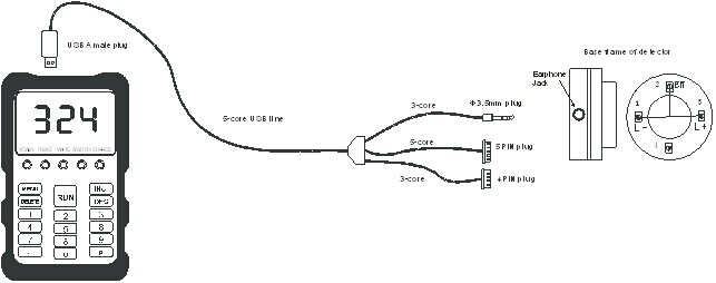
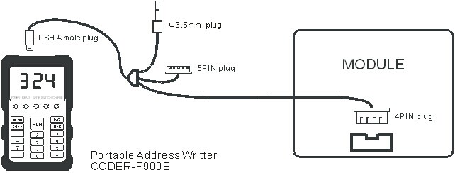
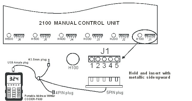
VII. Assembling of Peripheral Devices
As figure 2, figure 3and figure 4
1. Insert Φ3.5mm plug into the writing jack on the base frame of detectorto make reading/writing operation to the smoke detector and heatdetector;
2. Insert Φ3.5mm plug into the writing jack of handhold alarm or fireplugto make reading/writing operation;
3. 5PIN plugis used for 2100 system module;
4. Insert 5PIN plug intothe writing jack of handhold JTQ-BM-925T to make reading/writing operation;
5. 4PIN plugis used for intelligent module and audio/visual alarm.
VIII. Troubleshooting
1, It prompts “ERROR” when writing/reading
① Check whether the bus type is correct, it means 9000system is under working when the switching indicator turns off; 2100 system isunder working when the indictor blinks;
② Check whether the intelligent terminal is good, change aterminal device to have a test;
③ Check whether the connection is good; if the connectionline or coder doesn’t work, please contact our service center for help;
2, Fail to power on
Check whether the battery has enough power, connect withexternal power supply and try to power it on again; if still fails, pleasecontact our service center for help.
3, Buzzer beeps in successive
When the bus short circuit, the buzzer would beep insuccessive, at this moment the user should check whether the bus has short circuit,if not, please contact our service center for help.
IX. Precautions
1.Any other type of USB deviceis not allowed to connect with this product, otherwise it might damage your USBdevice.
2.Keep awayfrom corrosive liquids and do not use in wet, hot environment and strongmagnetic field.
3.Pleaseuse DC power adapter we provide, other types of power adapters might damagethis product.
4.Thiscoder is used only for the products our company produces; do NOT use it forthose produced by others.
